[Published: June 14, 2026 | Last updated: June 14, 2026] | 11 min read
TL;DR
- L1, L2, L3, and L4 refer to the first four layers of the OSI (Open Systems Interconnection) model — a seven-layer framework that describes how data travels between devices on a network (PhoenixNAP, 2025).
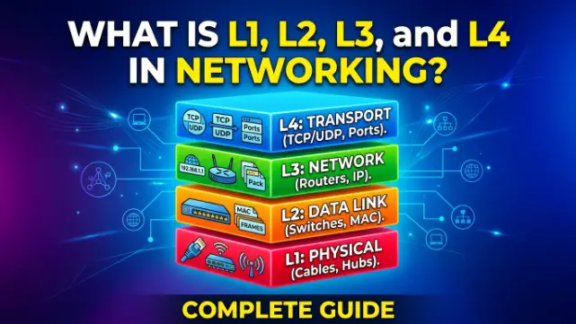
- L1 (Physical) handles raw electrical and optical signals — cables, voltage, fiber, and wireless radio waves. Devices: hubs, cables, access points.
- L2 (Data Link) handles node-to-node delivery using MAC addresses and frames. Devices: switches, bridges. Protocols: Ethernet, 802.1Q VLANs, STP.
- L3 (Network) handles logical addressing and routing across networks using IP addresses. Devices: routers, L3 switches. Protocols: IPv4, IPv6, OSPF, BGP.
- L4 (Transport) handles end-to-end delivery, segmentation, and reliability. Protocols: TCP (reliable) and UDP (fast). No dedicated hardware device — runs on endpoints.
- When a network problem occurs, IT engineers isolate it by layer: L1 means check cables; L2 means check MAC tables and VLANs; L3 means check IP and routing; L4 means check ports and firewall rules (NetAlith, 2026).
If you work in networking, cybersecurity, cloud engineering, or IT support, you will hear “check Layer 2” or “this is an L3 issue” in almost every troubleshooting conversation. These terms refer to the OSI model — a conceptual map that divides networking into seven distinct layers, each responsible for one part of moving data from one device to another. This guide explains L1 through L4 in plain language, with real devices, real protocols, and real troubleshooting logic at each layer.
What Is the OSI Model and Why Do Layers 1–4 Matter?
The OSI (Open Systems Interconnection) model is a seven-layer conceptual framework that standardizes how network devices communicate across different hardware and software systems (NetworkersHome, 2026). The International Organization for Standardization (ISO) published it in 1984 to solve a serious problem: before OSI, proprietary networking protocols from IBM, Digital Equipment Corporation, and Xerox couldn’t talk to each other without expensive custom gateways.
The model doesn’t describe a single technology. It describes the roles that any networking technology must perform. Each layer handles a specific job and passes data up or down to adjacent layers through a process called encapsulation (adding headers on the way down) and decapsulation (removing headers on the way up) (PhoenixNAP, 2025).
The seven layers are:
| Layer | Name | Key Responsibility |
|---|---|---|
| L7 | Application | User-facing protocols: HTTP, DNS, SMTP |
| L6 | Presentation | Encryption, compression, formatting |
| L5 | Session | Managing conversation sessions between apps |
| L4 | Transport | End-to-end delivery, TCP vs UDP |
| L3 | Network | IP addressing and routing between networks |
| L2 | Data Link | MAC addressing, frames, node-to-node delivery |
| L1 | Physical | Raw signals: cables, voltage, light, radio |
(PhoenixNAP, 2025; NetAlith, 2026)
Layers 1 through 4 matter most for network engineers, hardware teams, and security professionals because they cover the actual movement of data — physical transmission, device-to-device delivery, cross-network routing, and end-to-end reliability. Layers 5 through 7 sit higher and are primarily handled by application software rather than network hardware. Understanding L1–L4 is what gets you through CompTIA Network+, Cisco CCNA/CCNP, and most network engineering interviews.
L1: The Physical Layer
L1 is the Physical layer — the bottom of the OSI stack and the most literal. It handles the transmission of raw bits (0s and 1s) as electrical signals, light pulses, or radio waves between devices (CBT Nuggets, 2026).
L1 doesn’t care what those bits mean. It doesn’t read addresses, check errors, or make routing decisions. Its only job is to get the signal from Point A to Point B across a physical medium.
What L1 defines:
- Cable types and wiring standards — Cat6, Cat6A, fiber optic (single-mode and multi-mode)
- Connector types — RJ45, LC, SC fiber connectors
- Signal voltages and timing for copper cables
- Radio frequencies and modulation schemes for Wi-Fi
- Optical wavelengths for fiber optic transmission
- Maximum cable lengths — 100 meters for Cat6 Ethernet, kilometers for single-mode fiber
Devices that operate at L1:
Hubs, repeaters, modems, Ethernet cables, fiber optic cables, and wireless access points at their most basic level all operate at L1. A hub is the classic example: it receives a signal on one port and broadcasts it to every other port with no intelligence — no addresses read, no decisions made, just raw signal amplification and distribution (CBT Nuggets, 2026).
PDU (Protocol Data Unit) at L1: Bits.
Troubleshooting at L1:
When you suspect an L1 problem, check the physical medium first. Is the cable plugged in? Is the link light on? Is the cable damaged, too long, or the wrong type? Is the fiber connector dirty? Is the wireless signal too weak due to distance or interference? Every network problem starts with an L1 check because nothing above it works if the physical connection is broken.
L2: The Data Link Layer
L2 is the Data Link layer. It takes the raw bits from L1 and organizes them into frames — structured packages of data that include addressing information for delivery between two directly connected devices (Solo.io, 2025).
Where L1 moves signals, L2 moves frames between specific nodes. The address system at L2 is the MAC address — a 48-bit hardware address burned into every network interface card at manufacture. MAC addresses look like this: 00:1A:2B:3C:4D:5E. L2 uses MAC addresses to decide which specific device on the same network segment receives a frame.
L2 divides into two sublayers:
MAC (Media Access Control) — controls how devices gain access to the network medium and how MAC addresses are used for frame delivery. It also handles CSMA/CD (Carrier Sense Multiple Access with Collision Detection), the protocol Ethernet uses on half-duplex connections to manage collisions, though in modern Gigabit Ethernet this is effectively obsolete (CBT Nuggets, 2026).
LLC (Logical Link Control) — manages frame synchronization, flow control, and error checking between two directly connected nodes (Solo.io, 2025).
Key L2 protocols and technologies:
- Ethernet (IEEE 802.3) — the dominant L2 protocol for wired LANs
- 802.1Q VLANs — logical segmentation of a physical network into separate broadcast domains
- STP / RSTP / MSTP (Spanning Tree Protocol) — prevents loops in L2 networks by blocking redundant paths
- ARP (Address Resolution Protocol) — maps IP addresses to MAC addresses, sitting at the L2/L3 boundary
Devices that operate at L2:
Switches and bridges are the primary L2 devices. A switch reads the destination MAC address in each frame and forwards it only to the port where that MAC address is registered — not to all ports like a hub. This is what makes switches far more efficient than hubs: a 24-port switch handles 24 simultaneous conversations; a hub handling the same 24 ports broadcasts every frame everywhere (CBT Nuggets, 2026).
PDU at L2: Frames.
L3 segmentation reduces broadcast-related incidents by more than 60% in enterprise environments — which is why flat Layer 2 networks beyond 254 devices in a single VLAN create performance and stability problems (Network-Switch.com, 2026).
Troubleshooting at L2:
Check whether the switch has learned the correct MAC addresses. Check VLAN assignments — a device in the wrong VLAN can’t reach the rest of its network even if the cable is fine. Check STP state — a port stuck in blocking mode looks like a connectivity failure. Check for duplicate MAC addresses or port security restrictions blocking a specific device.
L3: The Network Layer
L3 is the Network layer. It handles logical addressing and routing — making decisions about how to move data between different networks, not just between directly connected devices (ExpertCisco, 2026).
Where L2 uses MAC addresses to deliver frames between nodes on the same network, L3 uses IP addresses to route packets between different networks. This is the fundamental difference. MAC addresses are local and hardware-assigned. IP addresses are logical, administrator-assigned, and work across the entire internet.
How L3 routing works:
When a packet needs to travel from a device in one network to a device in another, L3 devices examine the destination IP address and consult a routing table to determine the best path. Each hop — each router or L3 switch along the way — makes this decision independently. The packet may cross dozens of routers between source and destination (NetAlith, 2026).
Key L3 protocols:
- IPv4 — the dominant IP addressing protocol, using 32-bit addresses (e.g., 192.168.1.1)
- IPv6 — the successor to IPv4, using 128-bit addresses to handle address exhaustion
- ICMP — Internet Control Message Protocol; what
pingandtracerouteuse for diagnostics - OSPF (Open Shortest Path First) — a dynamic routing protocol for internal networks
- BGP (Border Gateway Protocol) — the routing protocol that controls how data moves between internet service providers globally
Devices that operate at L3:
Routers are the classic L3 device. An L3 switch is an L2 switch with routing capabilities added in hardware — it routes between VLANs and subnets at wire speed using ASICs rather than software, which makes it far faster than a traditional software-based router for internal traffic (Network-Switch.com, 2026). Firewalls also operate at L3 (and L4), making routing and access decisions based on source and destination IP addresses.
PDU at L3: Packets.
PDU naming matters for troubleshooting. A frame is L2. A packet is L3. A segment is L4. Engineers use these terms precisely in incident reports and configurations because they pinpoint exactly which layer is being examined or modified.
Troubleshooting at L3:
Use ping to test whether an IP address is reachable. Use traceroute to see exactly where packets are dropping. Check the routing table on routers and hosts. Verify subnet masks and default gateway settings on devices. Check ACLs (Access Control Lists) and firewall rules that may be blocking traffic at the IP level. Verify NAT (Network Address Translation) configuration if traffic crosses network boundaries.
L4: The Transport Layer
L4 is the Transport layer. It handles end-to-end delivery of data between applications running on two devices across a network — managing segmentation, reassembly, flow control, and (optionally) reliability (Servercore, 2025).
L4 introduces the concept of ports — numbered identifiers that distinguish which application on a device should receive specific traffic. IP addresses identify the device. Port numbers identify the application running on that device. A web server at 192.168.1.10 listening on port 80 (HTTP) is an L4-level address — IP plus port together.
The two L4 protocols:
TCP (Transmission Control Protocol) is connection-based and reliable. Before data transfers, TCP performs a three-way handshake (SYN → SYN-ACK → ACK) to establish a connection. It sequences packets, acknowledges receipt, retransmits lost data, and ensures everything arrives in the correct order. TCP is used for anything where data integrity matters: web browsing (HTTPS), email (SMTP), file transfer (FTP), database queries (ExpertCisco, 2026).
UDP (User Datagram Protocol) is connectionless and fast. No handshake, no acknowledgment, no retransmission. UDP just fires packets and assumes they’ll arrive. For data where a few lost packets matter less than delay — video streaming, VoIP calls, online gaming, DNS lookups — UDP’s lower overhead keeps latency down. A dropped video frame is less noticeable than a video call that stutters waiting for TCP retransmissions (Servercore, 2025).
Common port numbers at L4:
| Port | Protocol | Application |
|---|---|---|
| 80 | TCP | HTTP (web) |
| 443 | TCP | HTTPS (secure web) |
| 22 | TCP | SSH (secure shell) |
| 25 | TCP | SMTP (email sending) |
| 53 | UDP/TCP | DNS (domain name resolution) |
| 67/68 | UDP | DHCP (IP address assignment) |
| 3389 | TCP | RDP (remote desktop) |
| 443 | UDP | QUIC / HTTP/3 |
Devices that operate at L4:
No dedicated hardware device operates purely at L4. The transport layer is implemented in the operating system of endpoints — the TCP/IP stack on your laptop, server, or phone. Stateful firewalls inspect L4 headers to allow or block specific ports and connection states. Load balancers at L4 distribute incoming connections across multiple servers based on source IP and port, without inspecting the payload.
PDU at L4: Segments (TCP) / Datagrams (UDP).
Troubleshooting at L4:
Use netstat or ss on Linux to check which ports are open and which connections are established. If ping (L3) succeeds but a service is unreachable, the issue is L4 or above — a firewall blocking a port, the service not listening, or a TCP connection being refused. Check firewall rules for specific port blocks. Verify the application is running and bound to the correct port. If TCP connections drop mid-session, check for stateful firewall timeout rules or MTU mismatches causing fragmentation issues.
How L1–L4 Work Together: A Data Journey Example
Suppose you open a browser in Dhaka and load a web page from a server in Singapore. Here is what each layer does.
L7 → L4: Your browser (L7 Application) sends an HTTPS request. L4 wraps it in a TCP segment addressed to port 443 on the server’s IP.
L4 → L3: L3 adds an IP header with your source IP and the server’s destination IP. This is now a packet.
L3 → L2: L2 wraps the packet in an Ethernet frame with your MAC address as source and your router’s MAC as destination. This is now a frame.
L2 → L1: L1 converts the frame to electrical signals on your Ethernet cable or radio waves on your Wi-Fi, and transmits it to your router.
At your router: L1 receives the signal. L2 strips the Ethernet frame. L3 reads the IP destination, looks up the routing table, and decides the next hop. L2 creates a new frame for that next hop. L1 transmits it. This repeats at every router between Dhaka and Singapore.
At the server: the process runs in reverse — decapsulation from L1 up through L4, then the web server application at L7 reads the request and responds.
That round trip — across 14 hops, 4,000 km — takes roughly 40–60 ms. Each layer performed its role once, in sequence, at every device along the path.
L2 vs L3 Switches: The Practical Decision
In 2026, choosing between an L2 and an L3 switch is one of the most common network design decisions in enterprise environments.
Use an L2 switch when:
- Your network is a single subnet with no inter-VLAN routing needed
- You have fewer than ~254 devices in one broadcast domain
- Routing is handled by a separate firewall or router at the edge
- Budget is a priority and routing complexity isn’t needed
Use an L3 switch when:
- You need inter-VLAN routing — devices in different VLANs that must communicate
- Your campus or enterprise network has multiple subnets across multiple buildings
- You want to keep routing local and fast rather than hairpinning traffic through a central router
- You need dynamic routing protocols (OSPF, BGP) for redundancy and failover
L3 segmentation with proper routing boundaries reduces broadcast-related incidents by over 60% in validated enterprise deployments, and L3 switches perform routing in hardware ASICs at line-rate speeds — the old idea that “L3 is slower than L2” is outdated on any modern platform (Network-Switch.com, 2026; Telecomate, 2025).
A Short Case Study: Troubleshooting by Layer in a Dhaka Office
An IT support engineer at a garments company in Dhaka got a ticket: “Cannot access internal ERP system.” The engineer worked through the layers methodically.
L1 check: The user’s laptop showed a link light. Cable was plugged in. L1 clear.
L2 check: The engineer pinged the default gateway and it responded. But arp -a showed no entry for the ERP server’s IP — the switch wasn’t forwarding frames to that MAC address. Investigation revealed the user had been moved to a different desk, plugged into a port assigned to the guest VLAN, not the corporate VLAN. L2 VLAN misconfiguration.
Fixing the switch port’s VLAN assignment resolved the issue in two minutes. The ERP server was never down. The route was never broken. The problem existed entirely at L2 — and the engineer found it in under five minutes by working layer by layer rather than guessing.
That is the daily value of understanding L1–L4.
Quick Reference: L1–L4 at a Glance
| Layer | Name | Address Type | PDU | Key Devices | Key Protocols | Troubleshooting Tool |
|---|---|---|---|---|---|---|
| L1 | Physical | None | Bits | Hub, cable, access point | Ethernet physical, 802.11 radio | Cable tester, link light check |
| L2 | Data Link | MAC address | Frames | Switch, bridge | Ethernet, 802.1Q, STP, ARP | arp -a, switch MAC table, Wireshark |
| L3 | Network | IP address | Packets | Router, L3 switch, firewall | IPv4, IPv6, OSPF, BGP, ICMP | ping, traceroute, route table |
| L4 | Transport | Port number | Segments/Datagrams | Firewall (stateful), load balancer | TCP, UDP | netstat, ss, firewall logs |
Frequently Asked Questions About L1, L2, L3, and L4 in Networking
What do L1, L2, L3, and L4 mean in networking?
They refer to the first four layers of the OSI model: L1 is Physical (raw signal transmission), L2 is Data Link (MAC address-based frame delivery), L3 is Network (IP address-based routing), and L4 is Transport (TCP/UDP end-to-end delivery). The terms are used by engineers to quickly identify where a network problem exists or what level of networking a device operates at (PhoenixNAP, 2025).
What is the difference between L2 and L3 in networking?
L2 uses MAC addresses to deliver data between devices on the same network segment. L3 uses IP addresses to route data between different networks. L2 devices (switches) don’t make routing decisions. L3 devices (routers, L3 switches) do. If two devices are in different VLANs or different subnets, L3 routing is required for them to communicate (Network-Switch.com, 2026).
What devices operate at L1, L2, L3, and L4?
L1: hubs, cables, repeaters, wireless access points (at the physical level). L2: switches and bridges. L3: routers, Layer 3 switches, and firewalls operating on IP rules. L4: no dedicated hardware device — L4 is implemented in the TCP/IP stack on endpoints. Stateful firewalls and load balancers inspect L4 headers but aren’t exclusively L4 devices.
What is the difference between TCP and UDP at L4?
TCP is connection-based and reliable — it establishes a handshake, sequences data, acknowledges receipt, and retransmits lost packets. UDP is connectionless and fast — no handshake, no acknowledgment, no retransmission. TCP is used for web, email, and file transfer. UDP is used for video streaming, VoIP, gaming, and DNS where speed matters more than guaranteed delivery (Servercore, 2025).
What is a Layer 3 switch and how is it different from a router?
A Layer 3 switch is an L2 switch with routing capabilities built into its ASIC hardware. It routes between VLANs and subnets at wire speed — much faster than a software router. A router is better suited for edge functions like NAT, VPN termination, and WAN connections. In modern enterprise networks, L3 switches handle internal routing while dedicated routers or firewalls handle the internet edge (Network-Switch.com, 2026).
How do I troubleshoot a network problem using OSI layers?
Start at L1 and work up. Check the physical connection first (cable, link light). Check L2 if L1 is fine (MAC tables, VLAN assignments, STP state). Check L3 if L2 is fine (IP address, subnet, routing table, firewall rules). Check L4 if L3 is fine (open ports, TCP connection state, application listening). Most problems resolve at L1 or L2. L3 and L4 issues are usually misconfigurations rather than hardware failures (NetAlith, 2026).
Key Takeaways
- L1 (Physical), L2 (Data Link), L3 (Network), and L4 (Transport) are the first four layers of the OSI model — the layers that handle all actual data movement in a network.
- L1 carries raw bits. L2 carries frames between MAC addresses. L3 carries packets between IP addresses. L4 carries segments between application ports.
- Switches are L2 devices. Routers and L3 switches are L3 devices. No dedicated hardware device operates exclusively at L4.
- TCP at L4 is reliable but slower. UDP at L4 is fast but unguaranteed. Choose based on whether the application needs data integrity or speed.
- Troubleshoot by layer — L1 first, then L2, L3, L4. Most problems resolve at L1 or L2 and never require investigating higher layers.
- Understanding L1–L4 is foundational for CompTIA Network+, Cisco CCNA, cybersecurity certifications, and any network engineering or cloud infrastructure role in 2026.